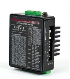
DRV-1
Step Motor Drive
User Manual

1776 Mentor Avenue
Cincinnati, Ohio 45212
Tel (513) 318-4600
DRV-1
Step Motor Drive
User Manual
1776 Mentor Avenue
Cincinnati, Ohio 45212
Tel (513) 318-4600
Contents
Introduction .......................................................................................................................... 3
Overview ............................................................................................................................. 3
Features ............................................................................................................................... 3
Safety Instructions ............................................................................................................. 5
Getting Started ................................................................................................................... 6
Mounting Hardware ................................................................................................................... 6
Choosing a Power Supply ......................................................................................................... 7
Voltage Selection .................................................................................................................. 7
Current ................................................................................................................................. 7
Connections .............................................................................................................................. 9
Connecting the Power Supply ................................................................................................. 10
Connecting the Inputs & Outputs ........................................................................................... 11
Connector Pin Diagram ....................................................................................................... 11
STEP & DIR Inputs .................................................................................................................. 11
EN Input ............................................................................................................................... 12
Switch Selecting .................................................................................................................... 13
Running Current ........................................................................................................................ 13
Microstep Setting ...................................................................................................................... 14
Self Test ...................................................................................................................................... 15
Step Smoothing Filter ..................................................................................................................... 15
Control Mode ................................................................................................................................... 15
MotorSelection ................................................................................................................................ 16
Troubleshooting ......................................................................................................................... 17
Reference Materials ................................................................................................................ 18
Technical Specifications ................................................................................................................ 18
Thank you for selecting the Resolution Air, Ltd. DRV-1 step motor drive. We hope our commitment to performance, quality and economy will make a successful motion control project.
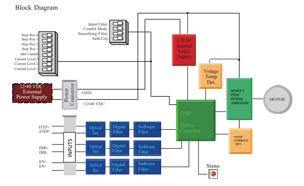
The DRV-1 Step motor drive is a cost-effective, high performance drive. The design is based on advanced digital current control technology, and features high torque, low noise and low vibration. Running current, microstep resolution, and other parameters are switch selectable so software configuration is not required.
Power Supply - Operates from a 12 to 40 volt DC power supply
Inputs - 3 optically isolated digital inputs, 5 to 24 volts
Speed Range - up to 3000 rpm
Current Control - 3 piano switch setting running current, 3 Amps peak maximum
Idle Current - Switch selectable for reduction to 50% or 90% of running current 1 second after the motor stops
Self-Test - Performs a 2 rev, 1 rps, CW/CCW move test, switch selectable: ON or OFF
Control Mode - Step & Direction mode, CW/CCW mode
Microstep Resolution - 4 piano Switch selectable, 16 settings: 200, 400, 800, 1600, 3200, 6400, 12800, 25600, 1000, 2000, 4000, 5000, 6000, 8000, 10000, 20000 steps/rev
DRV-1
|
I/O Configurations |
||
|
STEP(5-24V) |
DIR(5-24V) |
EN(5-24V) |
|
: Step Input |
: Direction Input |
: Enable Input |
|
: CW |
: CCW |
: Alarm Reset |
Only qualified personnel should transport, assemble, install, operate, or maintain this equipment. Properly qualified personnel are persons who are familiar with the transport, assembly, installation, operation, and maintenance of motors, and who meet the appropriate qualifications for their jobs.
To minimize the risk of potential safety problems, all applicable local and national codes regulating the installation and operation of equipment should be followed. These codes may vary from area to area and it is the responsibility of the operating personnel to determine which codes should be followed, and to verify that the equipment, installation, and operation are in compliance with the latest revision of these codes.
Equipment damage or serious injury to personnel can result from the failure to follow all applicable codes and standards. Resolution Air, Ltd. does not guarantee the products described in this publication are suitable for a particular application, nor do they assume any responsibility for product design, installation, or operation.
Read all available documentation before assembly and operation. Incorrect handling of the products referenced in this manual can result in injury and damage to persons and machinery. All technical information concerning the installation requirements must be strictly adhered to.
It is vital to ensure that all system components are connected to earth ground. Electrical safety is impossible without a low-resistance earth connection.
This product contains electrostatically sensitive components that can be damaged by incorrect handling. Follow qualified anti-static procedures before touching the product.
During operation keep all covers and cabinet doors shut to avoid any hazards that could possibly cause severe damage to the product or personal health.
During operation the product may have components that are live or have hot surfaces.
Never plug in or unplug the step motor drive while the system is live. The possibility of electric arcing can cause damage.
Be alert to the potential for personal injury. Follow all recommended precautions and safe operating practices. Safety notices in this manual provide important information. Read and be familiar with these instructions before attempting installation, operation, or maintenance.
The purpose of this section is to alert users to the possible safety hazards associated with this equipment and the precautions necessary to reduce the risk of personal injury and damage to equipment. Failure to observe these precautions could result in serious bodily injury, damage to the equipment, or operational difficulty.
To use the DRV-1 step motor drive, the following items are needed:
A 12 - 40 volt DC power supply, see the section below entitled “Choosing a Power Supply” for help in choosing the right one
Step & Direction signals
A small flat blade screwdriver for configuring the switches
2.1 MOUNTING HARDWARE
As with any step motor, the DRV-1 must be mounted so as to provide maximum heat sinking and airflow. Keep enough space around the Step motor drive to allow for airflow.

Never use the drive where there is no airflow or where other devices cause the surrounding air to be more than 40°C (104°F).
Never put the drive where it can get wet.
Never use the drive where metal or other electrically conductive particles can infiltrate the drive.
Always provide airflow around the drive.
2.2 CHOOSING A POWER SUPPLY
When choosing a power supply, there are many things to consider. If you are manufacturing equipment that will be sold to others, you probably want a supply with all the safety agency approvals. If size and weight are an issue get a switching supply. And you must decide what size of power supply (in terms of voltage and current) is needed for your application.
2.2.1 VOLTAGE SELECTION
Your motor can provide more torque at higher speeds if a higher power supply voltage is used .If you choose an unregulated power supply, make sure the no load voltage of the supply does not exceed the drive’s maximum input voltage specification.
2.2.2 CURRENT
The maximum supply current you could ever need is two times the motor current.
However, you will generally need a lot less than that, depending on the motor type, voltage, speed and load conditions. That’s because the DRV-1 uses a switching amplifier, converting a high voltage and low current into lower voltage and higher current. The more the power supply voltage exceeds the motor voltage, the less current you’ll need from the power supply. A motor running from a 40 volt supply can be expected to draw only half the supply current that it would with a 24 volt supply.
We recommend the following selection procedure:
If you plan to use only a few drives, get a power supply with at least twice “per phase” current rating of the step motor. Example: for a motor that’s rated for 2 A/phase use a 4A power supply.
If you are designing for mass production and must minimize cost, get one power supply with more than twice the rated current of the motor. Install the motor in the application and monitor the current coming out of the power supply and into the drive at various motor loads. This will tell you how much current you really need so you can design in a lower cost power supply.
Multiple Drives Sharing One Power Supply
Connections
3.1 CONNECTING THE POWER SUPPLY
If the power supply does not have a fuse on the output or some kind of short circuit current limiting device a fast acting fuse is required. A 3 Amp fast acting fuse should be installed in line with the“+” power supply lead.
Connect the power supply “+” terminal to the drive “ V+” terminal. Connect the power supply “-”
terminal to the drive “ V-” terminal.
Be careful not to reverse the wires. Reversing the connection may open the internal fuse and void the warranty.
If a regulated power supply is being used, there may be a problem with regeneration. When a load decelerates rapidly from a high speed, some of the kinetic energy of the load is transferred back to the power supply, possibly tripping the over-voltage protection of a regulated power supply, causing it to shut down.
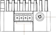
CONNECTING THE INPUTS & OUTPUTS
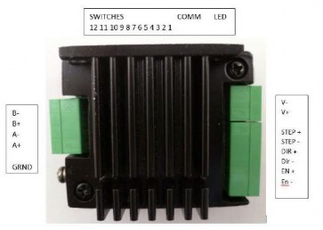
CONNECTOR PIN DIAGRAM
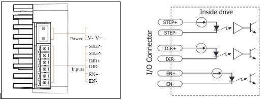
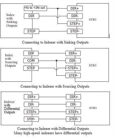
The DRV-1 step motor drive has two high speed optically isolated inputs called STEP and DIR. They accept 5 to 24 volt single-ended or differential signals, up to 500KHz. The maximum voltage that can be applied to the input is 28V.
The motor executes one step when the STEP input closes.
The direction of rotation is controlled by the DIR input state. A closed input (logic “0”) will result in clockwise rotation, and an open input (logic “1”) will result in counterclockwise rotation.
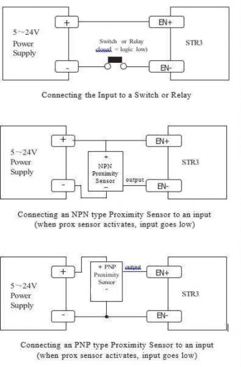
3.2.3 EN INPUT
The EN input enables or disables the drive Amplifier. It is an optically isolated input that accepts a 5 to 24 volt single-ended or differential signal. The maximum voltage that can be applied to the input is 28V.
When EN input is closed, the drive Amplifier is deactivated. All the MOSFETs will shut down, and the motor is free. When EN input is open, the drive is activated.
When the drive has encountered an error and the fault is removed from system, a falling signal into the EN input will reset the error status and activate the drive Amplifier again.
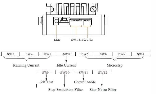
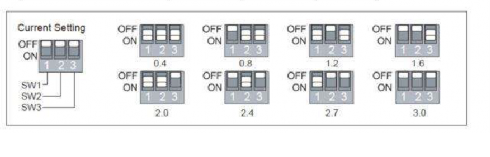
The output current of the DRV-1 step motor drive is set by the SW1, SW2 and SW3 switches and can be changed as necessary. There are 8 settings available according to the ON/OFF combination of the switches. Resolution Air, Ltd. MPPV-Series of valves are set to 0.4 Amp setting.
Current (Amps) |
SW1 |
SW2 |
SW3 |
0.4 |
ON |
ON |
ON |
0.8 |
OFF |
ON |
ON |
1.2 |
ON |
OFF |
ON |
1.6 |
OFF |
OFF |
ON |
2.0 |
ON |
ON |
OFF |
2.4 |
OFF |
ON |
OFF |
2.7 |
ON |
OFF |
OFF |
3.0 |
OFF |
OFF |
OFF |
4.2 IDLE CURRENT
The running current of the DRV-1 is automatically reduced whenever the motor isn’t moving. Setting the SW4 switch to ON maintains 50% of the running current. Setting this switch to OFF maintains 90% of the running current. This 90% setting is useful when a high holding torque is required. To minimize motor and drive heating it is highly recommended that the idle current reduction feature be set to 50% unless the application requires the higher setting.
50% 90%
DRV-1 setting switch SW5, SW6, SW7, SW8. There are 16 settings.
Steps/Rev |
SW5 |
SW6 |
SW7 |
SW8 |
200 |
ON |
ON |
ON |
ON |
400 |
OFF |
ON |
ON |
ON |
800 |
ON |
OFF |
ON |
ON |
1600 |
OFF |
OFF |
ON |
ON |
3200 |
ON |
ON |
OFF |
ON |
6400 |
OFF |
ON |
OFF |
ON |
12800 |
ON |
OFF |
OFF |
ON |
25600 |
OFF |
OFF |
OFF |
ON |
1000 |
ON |
ON |
ON |
OFF |
2000 |
OFF |
ON |
ON |
OFF |
4000 |
ON |
OFF |
ON |
OFF |
5000 |
OFF |
OFF |
ON |
OFF |
6000 |
ON |
ON |
OFF |
OFF |
8000 |
OFF |
ON |
OFF |
OFF |
10000 |
ON |
OFF |
OFF |
OFF |
20000 |
OFF |
OFF |
OFF |
OFF |
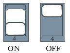
4.4 SELF-TEST
A built-in self-test feature is available on the DRV-1 to check the physical operation of the motor. Setting switch SW9 to ON after the drive is powered up will cause the drive to perform a self-test move of 2 revolutions both CW and CCW at 1rps. Setting switch SW9 to OFF disables this feature
![]()
![]()
Command signal smoothing can soften the effect of immediate changes in velocity and direction, making the motion of the motor less jerky. An added advantage is that it can reduce the wear on mechanical components. SW10 selects this function - ON enables it, OFF disables it.
This function can cause a small delay in following the control signal, and it should be used with that in mind.
![]()
![]()
ON OFF
Switch SW11 sets control mode. Switch OFF sets the Step & Dir mode. Switch ON sets the CW/ CCW mode.
Switch SW12 sets the digital signal filter. The STEP and DIR signal inputs have built-in digital filters and this setting will reduce external noise. If the system works on the low microstep, select the 150 KHz (ON) setting. If the system works on the high microstep, select the 500KHz (OFF) setting.
![]()
![]()
ON OFF
150KHz 500KHz
4.8 MOTOR SELECTION
Motor wires setting:
B- B+ A- A+
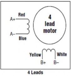
NOTE: MPPV-Series of Valves: A+(Red),A-(Black),B+(Blue),B-(Green)
MPPV-HR & PPV-HR Series: A+(Green),A-(Green w/White, B+(Red),B-(Red w/White)
LED Error Codes
Code |
Error |
|
|
Solid |
Motor Disabled |
|
Flashing |
Motor Enabled |
|
3 red, 1 green |
Over Temperature |
|
3 red, 2 green |
Bad Internal Voltage |
|
4 red, 1 green |
Power Supply Over Voltage |
|
4 red, 2 green |
Power Supply Under Voltage |
|
5 red, 1 green |
Over Current/Short Circuit |
|
6 red, 1 green |
Open Winding |
TECHNICAL SPECIFICATIONS
Power Amplifier |
|
Amplifier Type |
Dual H-Bridge, 4 Quadrant |
Current Control |
4 state PWM at 16 KHz |
Power Supply |
External 12 - 48 volt power supply required |
Input Voltage Range |
12 - 40 volts nominal, voltages outside this range will cause driver faults and/or may damage the drive |
Protection |
Over-voltage, over-current, under-voltage, over-temp, internal motor shorts (phase-to-phase, phase-to-ground) |
Ambient Temperature |
0 - 40°C (32 - 104°F) when mounted to a suitable heat sink |
Humidity |
90% non-condensing |
Controller |
|
Current Control |
Advanced digital current control provides excellent high speed torque |
Speed Range |
Speeds up to 3000 rpm |
Auto Setup |
Measures motor parameters to configure current control and anti-resonance gain settings |
Step Input STEP+/- |
Inputs: optically isolated, 5 - 24 volts, min. pulse width 250 us., max. pulse frequency 500KHz; motor executes one step when the STEP input closes |
Direction Input DIR+/- |
Inputs: optically isolated, 5 - 24 volts, min. pulse width 62.5 us., max. pulse frequency 500KHz; direction of rotation is controlled by the DIR input state |
Enable Input EN+/- |
Inputs: optically isolated, 5 - 24 volts, min. pulse width 500 us., max. pulse frequency 10 KHz; enables or disables the drive Amplifier |
Running Current |
Switch selectable, 8 settings: 3 Amps peak maximum |
Idle Current Reduction |
Automatically reduces the current 1 second after the motor stops; switch selectable, 2 settings: 50% or 90% of the running current |
Microstep Resolution |
Switch selectable, 16 settings: 200, 400, 800, 1600, 3200, 6400, 12800, 25600 1000, 2000, 4000, 5000, 6000, 8000, 10000, 20000 steps/rev |
Self-Test |
Checks internal and external power supply voltages, 2 rev move both CW and CCW at 1rps, switch selectable, ON or OFF |
Modes Of Control |
Step & Direction, CW/CCW control |
Drive Set-up
Resolution Air, Ltd. P.N. |
DVR-1 |
Stepper Drive Requirements |
See DRV-1 Manual for Complete Details |
Power |
12-40 VDC |
Input Signals |
Step, Direction, and Enable |
Input Signal Types |
Sinking, Sourcing, Differential |
Power Settings |
MPPV-HR: SW1,2,3=ON |
PPV-HR: SW1=Off, SW2 & 3=ON |
|
Idle Current |
SW 4=ON (50%) |
MicroStep |
Sw5,6,7,8 = On: Full Step |
Self Test |
SW9=Off: Disabled |
Smoothing Filter |
SW10 = On: Enabled |
Control Mode |
SW11 = OFF : Step/Dir |
Step Filter |
SW12 = on: 150 KHz |
Encoder-MPPV-HR |
U.S.Digital P.N.: E4P-200-197-N-S-H-D-B |
Encoder-PPV-HR |
U.S.Digital P.N.: E5-400-315-NE-S-H-D-B |
Stepper Motor Characteristics
Resolution Air, Ltd. P.N. |
MPPV-HR-E- |
PPV-HR-E- |
Actuator Size |
(0.8")Size 8 Hybrid Linear Actuator |
(1.4") Size14 Hybrid Linear Actuator |
Step Angle |
1.8 Degrees |
1.8 Degrees |
Wiring |
Bi-Polar |
Bi-Polar |
Operating Voltage |
5 VDC |
5 VDC |
Current/Phase |
0.24 A RMS |
0.57 A RMS |
Resistance/Phase |
20.4 Ω |
8.8 Ω |
Inductance/Phase |
5.0 mH |
13 mH |
Power Consumption |
2.45 W |
5.7 W |
Temperature Rise |
135° F. |
135° F. |
Isulation Resistance |
20 MΩ |
20 MΩ |
Rotor Inertia |
N/A |
27.0 gcm² |
Wiring Hookup |
A+(Grn),A-(Grn w/ White),B+(Red),B-(Red w/White |
A+(Grn),A-(Grn w/ White),B+(Red),B-(Red w/White |